ID21 BioPharma-BioSAXS (BioSAXS)
1. Introduction
The BioPharma-BioSAXS beamline performs overall structural characterization and structural transition studies of biological molecules in solution based on small angle X-ray scattering (SAXS) technique.[1, 2] SAXS measurement of samples in solution can obtain information with a resolution as low as 1-2 nm. It can be applied to a unique physiological solution environment where the physiological phenomena of biological molecules can be activated. It is possible to analyze the structural characteristics of crystalline/non-crystalline biological molecules under physiological conditions and conduct structural stability and structural transition studies under various experimental environmental conditions (temperature, pressure, pH, UV/Visible, ionic strength, ligand, electric field, magnetic field, etc.). Due to these advantages, the usability of the solution SAXS technique has greatly increased along with high-resolution structural analysis methods of biological molecules such as X-ray crystallography, nuclear magnetic resonance spectroscopy, and cryo-electron microscopy.[3] As a result, solution SAXS technique is being used as a standard analysis technique for structural characterization from biological molecules to nanostructure systems such as organic/inorganic nanoparticles, polymers, liquid crystals, colloids, and metals. Over the past 10 years, a dedicated BioSAXS beamline has been built at a world-class synchrotron radiation facility, contributing widely to the development of basic and applied science fields such as nanoresearch, structural biology, medicine, and new drug development. Recently, the biopharmaceutical field has begun to include the BioSAXS analysis technique in the workflow for analyzing the characteristics of biopharmaceutical for the purpose of identifying the structure, function, and operating principle of bio/protein therapeutics and providing evidence to prove the biological equivalence of biosimilars compared to original biopharmaceuticals. The BioPharma-BioSAXS beamline is classified and constructed as an industry priority support beamline to respond to the demands of industries in the bio and pharmaceutical fields and to promote manpower in related fields. The main strategy of the beamline is to process a large number of samples at high speed (high-throughput) in order to efficiently utilize high brilliance and low divergence X-rays based on 4th generation synchrotron radiation.[4]
2. Scientific objectives
The BioPharma-BioSAXS beamline provides a solution SXAS technique, contributing to the analysis of biopharmaceutical properties by studying the three-dimensional structure and structural transition of solution-phase biological molecules and their complexes. Examples of applications using the solution SAXS technique are as follows: (1) Quantitatively characterize the structure of multi-domain proteins linked by flexible linkers and intrinsically disordered proteins.[5-8] (2) Reveal the structural behavior and stability of proteins and protein drugs through understanding the structure of the native and denatured states of proteins.[9-11] (3) Recently, mRNA vaccines and treatments have been in the spotlight, and lipid nanoparticles (LNPs) are being used as an effective mRNA delivery system, and the structural stability of mRNA-LNPs in solution is being studied.[12, 13] (4) Real-time SEC-SAXS technique is used to study the change in solution phase structure of monodisperse biopolymer materials through separation/purification.[14] To facilitate such research, a collimated beam with high beam flux must be irradiated onto the sample. Varying the SDD is essential due to the diversity of samples to be measured and the need for a wide q range. A variable q range vacuum chamber will be built for fast and precise SDD change (0.5 - 6 m). By introducing an automatic sample changer at a fixed sample environment location, large number of samples can be processed at high speed to collect data at high throughput.
3. Beamline Requirements for the Insertion Device
The BioPharma-BioSAXS beamline will require the highest brilliance in the energy range of 5-20 keV without energy discontinuity. The source will be in-vacuum undulator with period length of 24 mm and total length of 3 m. A detailed description of the BioPharma-BioSAXS Insertion Device can be found in the [].
Table 1. Source Parameter for BioPharma-BioSAXS beamline
Undu lator |
Per iod ( mm) |
Len gth |
:s ub :` g` (m m) |
K : sub :m ax |
Po wer ( kW) |
Power density (kW mrad:s up:-2) |
Max. power after FE (kW) |
|---|---|---|---|---|---|---|---|
IVU24 |
24 |
3 |
5- 16 |
2. 747 |
1 7.9 |
165 |
0.87 Through 2(h)×2(v) mm2 FE mask |
4. Beamline Requirements for the Front End
The front end of BioPharma-BioSAXS beamline will require to handle a maximum power of 17.9 kW. The output of the beam from IVU24 is appropriately attenuated using three masks in the front end to prevent damage to the optical devices in the PTL section and enable stable operation of the beam line. The BioPharma-BioSAXS beamline will utilize the standard KOREA-4GSR IVU24 front end design. Two fixed type masks and one movable type mask will control a total of 17.5 kW of heat at the front end. The beamsize drawn from the front end will be 1.3 x 1.3 mm² at front end exit port. A detailed description of the BioPharma-BioSAXS Front End can be found in the [].
5. Beamline Layout
The BioPharma-BioSAXS beamline is a SAXS-dedicated beamline at the KOREA-4GSR construction. The beamline layout is shown in Figure 1, where the beamline will consist of a front end, an optical hutch, a photon transfer line, and an experimental hutch.
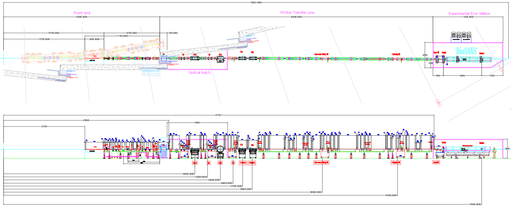
Figure 1. Layout of BioPharma-BioSAXS beamline
Table 2 shows major beamline components, their location along the beamline, and description.
Table 2. List of BioPharma-BioSAXS beamline component
Distance from source (m) |
Component* |
Description* |
Comments |
|---|---|---|---|
27.7 |
Attenuator |
Water cooled, CVD diamond, B 4C, Si |
Removing low energy X-ray beam |
28.3 |
Slit |
Water cooled, 4-way slit, UHV |
Eliminating heat load Mirror incident X-ray conditioning |
28.8 |
Diagnostic |
W-blade BPM |
Beam position & profile defining |
30.0 |
HHLM (High heat load mirror) |
Flat mirror 2-stripe coating (Pt, Rh) |
Eliminating heat load from X-ray |
32.2 |
Slit |
4-way slit, UHV |
Beam conditioning |
33.1 |
Diagnostic |
W-blade BPM |
Beam position & profile defining |
34.0 |
DCM (Double crystal mo nochromator) |
Si (111), fixed exit, NL2 cooled |
Monochromatizating X-ray beam |
35.9 |
Slit |
4-way slit, UHV |
Beam conditioning |
36.3 |
Diagnostic |
YAG + CCD |
Beam position & profile defining |
37.4 |
VFM (Vertical Focusing Mirror) |
Ellipsoid Rh, PT coating |
Focusing the beam in vertical direction |
39.1 |
HFM (Horizontal Focusing Mirror) |
Ellipsoid Rh, PT coating |
Focusing the beam in horizontal direction |
50.0 |
Slit |
4-way slit, HV |
Monochromatic beam conditioning |
50.9 |
Diagnostic |
YAG + CCD |
Beam position & profile defining |
57.0 |
Diagnostic |
OFHC + YAG |
Beam position & profile defining |
61.8 |
Slit |
4-way slit, HV |
Monochromatic beam collimation |
62.5 |
Diagnostic |
YAG + CCD |
Beam position & profile defining |
67.1 |
Shutter |
W |
Blocking the beam |
68.0 |
Slit |
4-way slit, HV |
Parasitic beam rejection |
69.0 |
Sample environment |
ARINAX robot |
Automatic sample exchanging system |
69.3~75.8 |
Variable q-range vacuum chamber |
7 m long SDD 0.5~6.0 m |
Detector position in vacuum tube SDD adjustment |
69.5~75 |
2D detector |
Eiger2 X 4M |
Scattering pattern detection |
6. Optics Overview
6.1 Mirror Specifications
Table 3 shows detailed specifications for optics.
Table 3. Specification for BioPharma-BioSAXS beamline optics
Property |
M1 |
M2 |
M3 |
|---|---|---|---|
Mirror system type |
HHLM |
VFM |
HFM |
Mirror size (W x L x D, mm) |
50 x 800 x 50 |
50 x 500 x 50 |
50 x 500 x 50 |
Optical footprint (W x L, mm) |
1.5 x 548 (4 sigma) |
1.08 x 392 (FWHM) |
1.06 x 433 (FWHM) |
Coating strip number |
2 ea |
2 ea |
2 ea |
Coating strip size (W x L, mm) |
10 X 800 |
10 X 500 |
10 X 500 |
Beam size (V X H) |
1.43 X 1.49 (4 sigma) |
1.02 X 1.08 (FWHM) |
1.06 X 1.13 (FWHM) |
Coating material |
Rh, Pt |
Rh, Pt |
Rh, Pt |
Substrate material |
Silicon |
Silicon |
Silicon |
Mirror surface shape |
Plane |
Ellipsoid |
Ellipsoid |
Reflection direction |
Up |
Down |
Ring |
Cooling method |
Eutectic bath |
No |
No |
Mirror bender |
Yes |
No |
No |
Tangential radius |
20 km |
Ra=34137.5, Rb=88.224 |
Ra=34775, Rb=89.7451 |
Sagittal radius |
|||
Tangential slope error (μrad) |
< 0.2 |
< 0.2 |
< 0.2 |
Sagittal slope error |
|||
Incident angle (mrad) |
2.6 |
2.6 |
2.6 |
Sample beam size (H X V, μm) |
32 X 9 |
32 X 9 |
32 X 9 |
Shot beam stability |
1 μm / 30 min |
1 μm / 30 min |
1 μm / 30 min |
Mirror surface height |
1400.0 |
1464.0 |
1464.0 |
Motor axis |
pitch, roll, x, y |
pitch, roll, yaw, x, y, z |
pitch, roll, yaw, x, y |
Manual axis |
pitch, roll, yaw, x, y, z |
pitch, roll, yaw, x, y, z |
pitch, roll, yaw, x, y, z |
Installation location |
30 |
37.5 |
39 |
Max. total heat load |
158.8 |
||
Max. surface heat load (W /mm2) |
0.216 @ 4 keV |

Figure 2. Reflectivity of Si, Rh, Pt surface at 2.6 mrad of incidence angle
6.2 High Heat Load Mirror
A high heat load mirror (HHLM) will be located 30 m from the light source. This mirror receives the beam from the front end and reflects it in the vertical direction. The beam in the high photon energy is absorbed, lowering the heat load on the monochromator crystal of the double crystal monochromator (DCM) located behind it. BioPharma-BioSAXS beamline will use silicon (Si), rhodium (Rh), and platinum (Pt) mirror surfaces depending on the beam energy to be used. This mirror is coated with two lines of rhodium and platinum on a single silicon substrate, and the uncoated side is used as a Si mirror surface. The beam incidence angle of the mirror surface is 2.6 mrad, and Figure 2 shows the reflectivity of each mirror surface material. The Si mirror surface absorbs beams above 12 keV and reduces the thermal load on the DCM crystal surface. Because high reflectivity (> 0.9) occurs in the 5 to 10 keV region, a Si mirror surface is used when using beams in this region. According to a similar principle, the Rh-coated side is used when using a beam in the 10 to 20 keV range, and the Pt-coated side is used when using a beam of 20 keV or higher.
The specifications of HHLM are listed in Table 3. When the white beam size is 1.43 mm X 1.49 mm (V x H) and incident angle is 2.6 mrad on HHLM, the foot print is 1.5 mm x 548 mm. The size of the coating surface is set to 10 mm x 800 mm to accommodate the entire incident beam. The amount of heat absorbed by the mirror surface was predicted using the SRW code in OASYS. The maximum total heat output was calculated to be 158.791 W, and the maximum heat output was calculated to be 0.216 W/mm2. The silicon substrate size of the mirror is 50 mm x 800 mm x 50 mm. The shape uses a cooling method using indium foil, Cu pad, and cooper pipe by digging a notch groove on the side of the mirror.
6.3 Focusing mirrors
To focus the beam at the sample location, place a vertical focusing mirror (VFM) at 37.5 m from the light source and a horizontal focusing mirror (HFM) at 39 m. Both of these mirror devices are curved in the beam direction (tangential ellipse). The beam is focused at 69 m, which is the sample location, and the distance between the focusing positions from the focusing mirror is 31.5 m for VFM and 30 m for HFM. As with HHLM, the incident angle is set to 2.6 mrad, and two lines of Rh and Pt coating are applied, respectively. Through this, harmonics are removed once more. <Table 2.2.1.8> shows the specifications of the beam focusing mirror device. The size of the focused beam at the sample location of 69 m is 31 μm horizontally and 9 μm vertically at half maximum.
6.4 Double Crystal Monochromator (DCM)
The double crystal monochromator (DCM) for monochromator adopts a structure that reflects the beam in the vertical direction, and the monochromator crystal uses silicon with a (111) reflection surface. Since the vertical beam spread of the incident light in the 5-20 keV range is less than 15 μrad, the resolution (ΔE/E) of the monochromatic photon energy is expected to be less than 2.0×10⁻⁴. The resolution of DCM was calculated by the following equation.
where, θB is the Bragg angle (or beam incidence angle) of the first DCM crystal, ωD is the Darwin width of the Si crystal, and ϕ is the beam spread angle.
The tilt of the crystal (pitch angle or pitch) is adjusted in the range of 5.7-23.3° to meet the photon energy range of 5-20 keV. The size of the incident beam is 1.5 mm in the horizontal direction x 1.5 mm in the vertical direction. To accommodate the beam in the entire photon energy range, the size of the first crystal is 60 mm x 25 mm, and the second crystal receives the beam reflected from the first crystal. The length is set to 150 mm so that the step can be maintained at 25 mm while accommodating it. To precisely control the direction of the emitted light, the pitch angle and roll angle of the second crystal are driven by a piezoelectric actuator. Changes in the position of DCM emitted light are checked in the diagnostic device UHV-QPBM, and a feedback system is configured to keep the beam position constant.
Table x. specification of DCM in BioPharma-BioSAXS beamline
6.5 Beam quality
Beam flux and beam profile at each optics
Reference
[1] FEBS Letters, 589, 2570-2577 (2015)
[2] Chemical Reviews 116, 11128-11180 (2016)
[3] Nature Methods 6, 606 (2009)
[4] Current Opinion in Structural Biology 58, 197-213 (2019)
[5] Structure 22, 1862–1874 (2014)
[6] Scientific Reports 11, 5655 (2021)
[7] Journal of American Chemical Society 142, 15697−15710 (2020)
[8] Journal of American Chemical Society 143, 20109−20121 (2021)
[9] Physical Chemistry Chemical Physics 19, 17143—17155 (2017)
[10] Polymers 11, 2104 (2019)
[11] Molecular Pharmaceutics 17, 2809–2820 (2020)
[12] PNAS 115, E3351-E3360 (2018)
[13] ACS Nano 15, 6709−6722 (2021)
[14] Bioinformatics 34, 1944-1946 (2017)