ID03 Coherent X-ray Diffraction (CoXRD)
1. Introduction
2. Scientific Objective
The coherent X-ray diffraction beamline is one of the most active beamlines utilizing the coherence characteristics of the 4GSR light source. This beamline focuses on supporting coherent X-ray diffraction imaging and microbeam diffraction research by highly focusing light sources with excellent coherence. Additionally, we plan to support real-time X-ray diffraction research using a diffractometer.
This beamline will provide a spatial resolution of less than 10 nm for coherent X-ray diffraction imaging. In Korea, Bragg CDI, one of the advanced techniques in coherent X-ray diffraction imaging, is actively used in research on secondary battery, catalyst, and semiconductor materials. This imaging technique enables the study of dynamic processes such as complex structures, defect formation and growth, and material changes. Furthermore, it greatly contributes to understanding the properties of various materials by vhgkddirectly observing microscopic physical phenomena at the nanoscale. These observations can be applied to various fields, including industrial applications and the development and application of next-generation materials. This beamline aims to increase the utilization of coherent X-ray diffraction imaging and microbeam X-ray diffraction.
3. Beamline Requirements for the Insertion Devices
ID03 will be installed in-vacuum undulator with a period of 22 mm of 3 m length.
The ID of the ID03 beamline is available in a continuous energy range and from 3 keV.
Beamline |
Und ulator |
** Period** (mm) |
** Length** (m) |
Max Power (kW) |
Max K value |
|---|---|---|---|---|---|
Coherent X-ray D iffraction |
I n-vacuum |
22 |
3 |
15.165 |
2.315 |
4. Beamline Requirements for the Front End
The FE of this beamline is designed for all optical component under the following conditions. (Reference the 4GSR beamline FE section)
Structural stress due to heat load should not exceed the yield strength.
The temperature rise due to heat load should not exceed the softening temperature of the materials.
The LCW temperature of the wall should not exceed the boiling point of water.
The maximum power drawn from the IVU22 is 15.165 kW, and the overall power is gradually removed in the FE. The power of the beam ultimately emitted from the FE is 120 W. The FE Movable Mask is located right in front of the photon shutter at the end of the FE, where it roughly conditions the beam to FWHM before it is incident on the PTL.
5. Beamline Layout
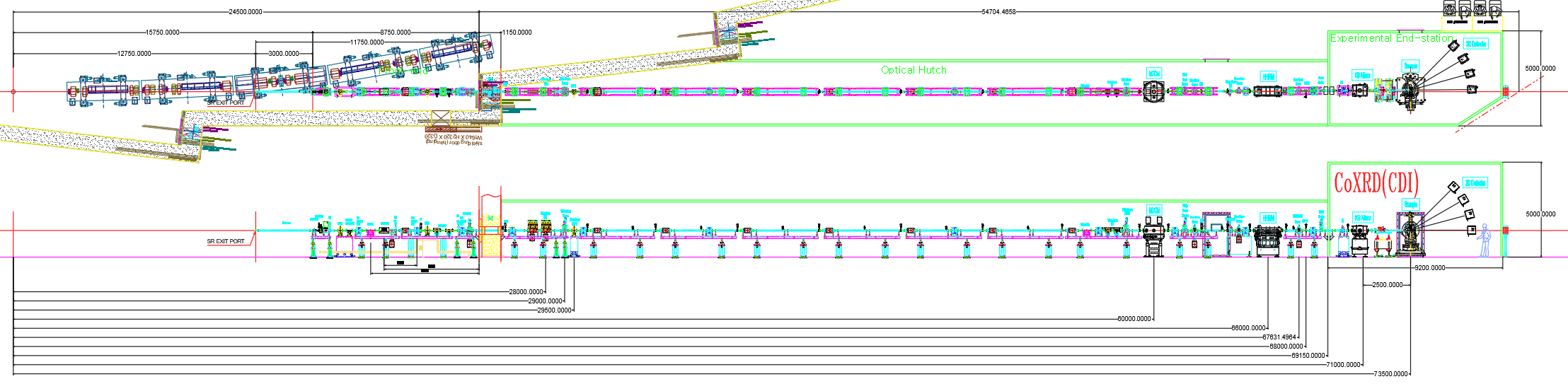
Di stance (m) |
Component |
Description |
|---|---|---|
22.5 |
Movable mask |
4-way slit, UHV, Water cooling |
23.8 |
Safety shutter |
|
28 |
White beam filter |
Graphite : 0.5 mm, 1 mm, 2 mm Diamond : 0.1 mm, 0.2 mm, 0.5 mm |
29 |
White beam screen |
Diamond window, Fluorescent metal screen, current signal output |
29.5 |
White beam PBPM |
4-Blade-type |
56.5 |
ID Photon shutter |
|
57.9 |
White beam slits |
4-way slit, UHV, Water cooling |
58.6 |
White beam screen |
Diamond window Fluorescent metal screen, current signal output |
60 |
HDCM |
Si (111), fixed exit |
61.7 |
White beam screen |
Diamond window Fluorescent metal screen, current signal output |
62.1 |
Mono beam screen |
YAG window Fluorescent metal screen, current signal output |
62.5 |
FCS |
|
64.1 |
Mono beam slits |
4-way slit, UHV |
64.5 |
Mono beam screen |
YAG window Fluorescent metal screen, current signal output |
66 |
High harmonics rejection mirror |
2-stripe coating (Pt, Rh) |
67 |
Mono beam slits |
4-way slit, UHV |
67.6 |
Mono beam screen |
YAG window Fluorescent metal screen, current signal output |
68 |
Beam position monitor |
UHV QBPM, Ti foil : 500 nm / Ni foil : 500 nm |
68.8 |
Hutch shutter |
|
70.3 |
Slits |
4-way slit, UHV |
71 |
KB mirror |
2-stripe coating (Pt, Rh), Vertical/Horizontal focusing, Pair |
Be window |
Double-side polished, 127-um-thick |
|
Slits |
4-way slit, HV |
|
Beam position monitor |
HV QBPM, Ti foil : 500 nm / Ni foil : 500 nm |
|
Attenuator |
8-channel (Al, Mn + block) |
|
73.5 |
Kappa diffractometer |
LM-guide or Air-bearing base plate |
6. Optics Overview
This beamline should be designed to maintain the wavefront to the sample. Therefore, the optics are designed to minimize vibration(<100 nrad) and mirror surface slope errors(<0.1 urad).
6.1 Optics Specifications
Rejection Mirror)
DCM
M1
Distance
(m)
60
66
Incidence Angle
(mrad)
2.5 – 4.1
Shape
Plane
Flat
Surface Normal direction
Horizontal
Horizontal
Substrate
Si (111)
Si
Coating Materials
(Thickness, nm)
Rh (50), Pt (50)
Substrate size (L × W)
(mm × mm)
1st : 50
2nd : 150
800 × 50
Roughness
(nm, RMS)
< 0.5
< 0.2
Slope error
(urad, RMS)
< 1
< 0.1
The monochromator will be used as the DCM(Double Crystal Monochromator), which has high energy resolution, and the crystal is Si(111), covering the energy range of 3-30 keV. Recently manufactured DCM, made with Si(111), can cover high energy, and optics designed with Si(111) is mechanically more stable compared to those using Si(111) and Si(311) pairs.
Energy range |
3 ~ 30 keV |
|---|---|
Crystal |
Si (111) |
Bragg angle |
41.234°~ 3.779° |
Angel resolution |
< 0.25 μrad |
Offset |
25 mm |
Motion axis |
Bragg, gap, roll, pitch, piezo roll and pitch for feedback |
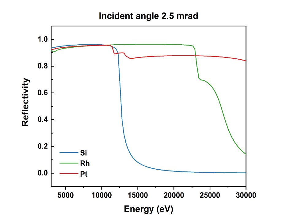
The high harmonics rejection mirror is located behind the monochromator serves to suppress the high harmonics energy of the beam coming out of the monochromator. Silicon crystal is FCC (Diamond structure). According to the diffraction selection rule, if h, k, and l are all odd or all even, and h+k+l is a multiple of 4, then n times the corresponding energy. High energy has a high transmittance, so even if it is slightly reflected, it affects the diffraction data. Therefore, a mirror coated with bare Si, Rh, and Pt is used and usually the incidence angle is 2.5 mrad. The reflectivity according to energy is shown in figure 2. The available energy range for each coating material is 5 to 12 keV for Si (reflectivity greater than 90%), 11 to 23 keV for Rh (reflectivity greater than 90%), and 15 to 30 keV for Pt (reflectivity greater than 80%). The incidence angle of 2.5 mrad is basically an angle calculated to enable use up to 30 keV, which is the target energy of this beamline. When using tender energy, the incidence angle must be changed up to 4.07 mrad to reduce the reflectivity of the harmonic energy corresponding to the tender energy by 10%. When using a bare-Si Mirror, the incidence angle-reflectivity result according to energy is shown in figure 3.

KB (VFM) |
KB (HFM) |
|
|---|---|---|
Distance (m) |
70.62 |
71 |
Incident Angle |
2.5 mrad |
2.5 mrad |
Shape |
Elliptical cylinder |
Elliptical cylinder |
Semi-major axis (mm) |
36750 |
36750 |
Semi-minor axis (mm) |
35.6533 |
33.3072 |
Surface Normal direction |
Vertical |
Horizontal |
Substrate |
Si |
Si |
Coating Materials (Thickness, nm) |
Rh (50), Pt (50) |
Rh (50), Pt (50) |
Substrate size(L × W) (mm × mm) |
330 |
330 |
Focus distance (m) |
2.88 |
2.5 |
Roughness (nm) |
< 0.2 |
< 0.2 |
Slope error (μrad, RMS) |
< 0.1 |
< 0.1 |
The KB mirror system for the this beamline
6.2 Optical Simulation and Tolerances