BM10 High Energy Microscopy (HEM)
1. Introduction
High-energy microscopy is one of the long beamlines exceeding 100 meters, providing CT images based on projection image technology. Imaging is performed in a monochromatic beam range of 5 to 40 keV and a white beam range of up to 100 keV, with photons supplied from a central bending magnet. The High-Energy Microscopy beamline consists of two optical hutches and one end station. The first optical hutch is located in an experimental building (storage building) approximately 27 meters from the source, and the other two are located in separate buildings at 85 meters and 95 meters, respectively. A separate building is shared with another long beamline, the ID10 nano-probe beamline.
2. Scientific objectives
Synchrotron source provide highly brilliant and collimated X-rays, which are essential for achieving high-resolution imaging. Microtomography (μCT) using synchrotron radiation has significantly advanced the nondestructive three-dimensional imaging capabilities across various scientific disciplines such as medicine, biology, and materials science. Superior imaging capabilities allow for detailed studies of internal structures such as porosity, grain morphology, and defects without destructive sample treatment. The transition from incoherent to coherent X-ray sources will open up new scientific discoveries and possibilities in medicine, biology and materials science.
2.1 Improved Contrast and Resolution Imaging
Synchrotron-based μCT continues to evolve with advancements in X-ray sources and imaging techniques. Due to the divergence of the incoherent X-ray source, the spatial resolution achievable in the tomogram is limited to about 2 μm. Increasing the coherence of the X-ray beam is expected to significantly improve spatial resolution. Phase contrast imaging utilizes increased photon flux and coherence ratio to improve spatial resolution and contrast. This technique improves sensitivity to structural changes in the specimen while minimizing its impact on the sample. Improved spatial resolution and sensitivity allow researchers to resolve finer structural details in three-dimensional imaging, expanding the range of observations in materials and biological specimens.
2.2 4D Materials Science (Dynamics study of in-situ/operando)
Imaging beamlines utilizing 4th generation light sources can be optimized for performing μCT on bulk samples. Enhanced photon flux and contrast improve acquisition times for dynamic imaging, supporting rapid data acquisition for materials modeling and validation. This enables real-time 3D imaging (4D) of materials behavior, facilitating direct comparison between experimental and simulated data.
2.3 Multiscale Imaging
Multiscale imaging provides wide spatial resolution in absorption and phase contrast imaging, enabling detailed studies of microstructures ranging from hundreds of nanometers to several millimeters. This approach implies a comprehensive understanding of material structures and processes.
3. Beamline Requirements for the Insertion Device (Bending magnet)
High-energy microscope beamlines require high-brightness sources that can cover the X-ray energy spectrum from 5 keV to over 100 keV and small source sizes to maximize phase contrast effects. To meet these requirements, bending magnets or superbend magnets are needed that can provide high fields at short device periods.
Bending magnets are essential components of synchrotron facilities used to steer electron beams along circular paths, and the performance of the magnets is critical to the overall functioning of the beamline in terms of brilliance and flux. Figures 1 and Table 1 illustrate the brilliance and flux curves for bending magnets, showing their capabilities at various photon energies.


Figure 1. Predicted brilliance and flux of the Insertion Devices.
Table 1. Source Parameters for HEM beamline.
Source Type |
Magnetic Field |
Magnetic Radius |
Total Power |
Critical Energy |
|---|---|---|---|---|
Bending magnet |
2T |
6.67 m |
1.36 kW |
21 keV |
Bending magnets have magnetic fields as high as 2 Tesla, with a critical energy of 21 keV and a usable energy range of up to 100 keV. The extended energy range covering up to 100 keV supports a wide array of experimental techniques and applications, including studies of dense materials and high-energy processes. High flux and brightness enable more detailed, higher resolution imaging and analysis, which are essential for advancements in materials science, biology, and chemistry.
Bending magnets can be upgraded to superbend magnets in the future to provide an immediate improvement in beamline performance while preserving the existing beamline design. Superbend magnets are specialized magnets designed to enhance the performance of synchrotron beamlines by generating higher flux and brilliance, particularly at higher photon energies. High photon energy allows for more accurate and detailed investigations in various scientific domains such as imaging, X-ray absorption fine structure (XAFS), and scattering. We anticipate meeting future scientific requirements by keeping open the option to upgrade our imaging beamline.
4. Beamline Requirements for the Front End
The layout of the beamline is split into two parts separated by a ratchet-shaped storage ring tunnel wall, and the inside of the ring tunnel wall is the front-end (FE). The FE is designed to protect both personnel and equipment on the beamline, as well as the machinery in the event of a vacuum failure on the beamline.
The HEM beamline requires a new high heat load front end capable of handling a total power of 1.36 kW with a beam divergence of 2.0 mrad horizontally and 0.3 mrad vertically. The front end of the HEM beamline is designed to respond to beamline issues while minimizing entry and exit. Table 2 shows an overview of the components and functions of the HEM beamline front end.
Table 2. Component list of the front-end in the HEM beamline
Distance from source (m) |
Component |
Description/Comments |
|---|---|---|
0 |
Bending magnet |
Source (2 T) |
12 |
Parastic Mask |
|
12.5 |
Beam stopper |
Absorb of high-energy Bremsstrahlung radiation |
13 |
PBPM1 |
Diamond-blade |
14 |
Safety Magnet |
Electron Stop |
14.5 |
Diamond window |
Vacuum separate |
15 |
Photon Shutter 1 |
Main beam blocking |
16 |
Photon Shutter 2 |
spare component |
19 |
PBPM2 |
diamond-blade |
21 |
Safety Shutter 1 |
beam diagnostics & Shockwave Blocking |
22 |
Safety Shutter 2 |
spare component |
5. Beamline Layout

Figure 2. Layout for High Energy Microscopy beamline
The High Energy Microscopy beamline will be one of two long beamlines built at the Korea-4GSR. Located at BM-10, High Energy Microscopy beamline extends beyond the exterior wall of the storage ring building, allowing for a sample position that is located at 100 meters from source.

Figure 3. Conceptual layout of the High Energy Microscopy beamline indicating diagnostics, x-ray optics, sample location, and detector.
The conceptual layout of beamline shown in Figure 3 displays x-ray optics, sample environments, and detector.
5.1 Beamline Component Table
Table 3 shows all major beamline components and lists them in order of distance from the source.
Table 3. High Energy Microscopy beamline component table
Lo cation |
D istance from source (m)* |
Component* |
Description/Comments |
|---|---|---|---|
Front End (0 - 23 m) |
0 |
Source |
Bending magnet (2T) |
12 |
Parastic Mask |
|
|
12.5 |
Beam stopper |
Absorb of high-energy Bremsstrahlung radiation |
|
13 |
PBPM1 |
Diamond-blade |
|
14 |
Safety Magnet |
Electron Stop |
|
14.5 |
Diamond window |
Vacuum separate |
|
15 |
Photon Shutter 1 |
Main beam blocking |
|
16 |
Photon Shutter 2 |
spare component (Photon Shutter) |
|
19 |
PBPM2 |
diamond-blade |
|
21 |
Safety Shutter 1 |
beam diagnostics & Shockwave Blocking |
|
22 |
Safety Shutter 2 |
spare component (Safety Shutter) |
|
Wall (23 - 24.8 m) |
23 - 24.8 |
Wall |
Front End Radiation blocking |
Optical Hutch 1 (24.8 - 30 m) |
25 |
Slit |
Beam size defining and heat absorption |
26 |
Diagnostics |
beam diagnostics |
|
28 |
Filter Array |
White Beam Filter (low energy cut-off) |
|
Long spool (30 - 88 m) |
45 |
Long spool |
Beam transfer (UHV) |
Optical Hutch 2 (88 - 98 m) |
88 |
Slit |
DMM Beam size defining |
89 |
Diagnostics |
beam diagnostics |
|
90 |
onochromator |
Double Multilayer Monochromator (5 – 40 keV) |
|
93 |
Diagnostics |
beam diagnostics |
|
94 |
White Beam Block 1 |
Movable white beam / Bremsstrahlung stop |
|
94.5 |
White Beam Block 2 |
spare component (White Beam Block) |
|
95 |
Hutch Shutter |
White / Mono beam stop |
|
96 |
Exit slit |
Final Beam size defining |
|
97 |
Exit window |
Be window (UHV, > 200 mm, water cooled) |
|
98 |
Ion gas chamber |
beam diagnostics (mono beam, I0) |
|
Exp. Hutch (98 - 121 m) |
100 |
Sample stage 1 |
Heavy Load Air-Bearing Stage |
102 |
Sample stage 2 |
Light Load Air-Bearing Stage |
|
104 – 119 |
Detector station |
Phase contrast effect |
|
104.5 - 116.5 |
Detector 1 |
Mono-beam X-ray microscope (High magnification) |
|
105.5 – 117.5 |
Detector 2 |
White-beam X-ray microscope (High magnification) |
|
106.5 – 118.5 |
Detector 3 |
Large FOV lX-ray microscope (Low magnification) |
|
121 |
Beam Stop |
White Beam Stop, Fixed, Cooled |
6. Optics Overview
6.1 Beam Delivery Specifications
The energy range of the HEM beamline is from 5 keV to 100 keV and is planned to operate in monochromatic mode from 5 keV to 40 keV and in white beam mode above 40 keV.
6.1.1 Monochromatic beam mode
Monochromatic mode using a DMM provides a narrow band of optimized energy for experiments. Because the size of the available beam is structurally limited in DMM, the incident beam size must be defined using a slit.
6.1.2 White beam mode
In white beam mode, a low energy cut-off filter is used to optimize the beam energy. The opening beam size of the bending magnet is maintained at 2 m rad in the horizontal direction and 0.3 m rad in the vertical direction. Consequently, at the sample position, which is located 100 meters from the light source, a beam size of 200 x 30 mm is achievable.
The beam performance of Monochromatic beam and white beam mode are controlled by slit’s, filers, and DMM, and the expected performance and parameters are shown in Table 4.
Table 4. Performance parameters of Monochromatic beam and white beam mode in the HEM beamline.
Beam mode |
D istance from source (m)* |
Component* |
Beam size FWHM (H x V, mm) |
Beam Power (abs., W) |
|---|---|---|---|---|
White beam |
0 |
Source |
0.011 x 0.0099 |
389.0 |
14.5 |
Diamond window |
29 x 4.35 |
387.0 (49.3) |
|
25 |
4-Slit |
50 x 7.5 |
337.8 (0) |
|
28 |
|
56 x 8.4 |
337.7 (303.7) |
|
88 |
4-Slit |
176 x 26.4 |
34.0 (0) |
|
90 |
DMM |
180 x 27 |
34.0 (0) |
|
96 |
4-Slit |
194 x 29.1 |
34.0 (0) |
|
97 |
Be window (1mm) |
196 x 29.4 |
34.0 (0.6) |
|
100 |
Sample |
200 x 30 |
33.4 (0) |
|
121 |
Beam stop |
242 x 26.3 |
33.4 (33.4) |
|
Mono beam |
0 |
Source |
0.011 x 0.0099 |
389.0 |
14.5 |
Diamond window |
29 x 4.35 |
387.0 (49.3) |
|
25 |
4-Slit |
25 x 3.8 |
337.7 (102.9) |
|
28 |
Attenuator |
28 x 4.2 |
127.8 (0) |
|
88 |
4-Slit |
10 x 2 |
127.8 (125.2) |
|
90 |
DMM |
10 x 2 |
2.6 (2.5) |
|
96 |
4-Slit |
10.6 x 2.1 |
0.1 (0) |
|
97 |
Be-window |
10.8 x 2.1 |
0.1 (0) |
|
100 |
Sample |
11.1 x 2.2 |
0.1 (0) |
|
121 |
Beam stop |
13.3 x 2.6 |
0.1 (0.1) |
6.2 Detailed Optical Layout
6.2.1 Ray-tracing (Horizontal, Vertical)
Optics configuration for projection imaging in Monochromatic beam and white beam modes is shown in Figure 4.

Figure 4. Optics configuration (horizontal/upper, vertical/lower) for projection imaging.
6.3 Optics Specifications
6.3.1 Windows
The window located at the front-end of beamline plays a critical role in the thermal load and maintaining optimal beamline conditions. It protects sensitive downstream components by reducing the thermal load before the beam reaches the white beam slit, filter and monochromator.
CVD diamond (Chemical Vapor Deposition) is known for its high thermal conductivity and low absorption, making it suitable for managing high thermal loads without significant beam attenuation. These CVD Diamond windows are designed to maintain performance under high heat load conditions.
CVD diamond windows are used to separate the UHV (ultra-high vacuum) of the accelerator ring from the beamline, providing vacuum protection in case of a vacuum failure on the beamline. These windows have a maximum aperture of 38 x 9 mm, which is sufficient to pass the beam, and they also reduce the heat load by 60W.
6.3.2 Filters
In high-energy imaging beamlines, a low energy cut-off filter is an essential component designed to remove unwanted low-energy photons from the beam. This helps to optimize the beam quality and ensure that only the desired high-energy photons are used for imaging. The low energy cut-off filter selectively absorbs or reflects photons below a certain energy threshold, allowing only higher-energy photons to pass through.
By removing low-energy photons, the filter reduces background noise and enhances the signal-to-noise ratio (SNR) of the imaging system. This results in clearer and more accurate images. Low-energy photons contribute significantly to the thermal load on downstream optical elements and detectors. Filtering these photons reduces the heat load, thereby protecting sensitive components and enhancing their longevity and performance.
The beam performance of HEM beamline is controlled by filters and the expected performance are shown in Figure 5.
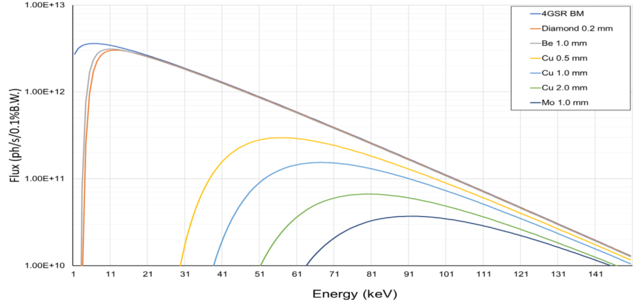
Figure 5. Performance of beam by filter material in the HEM beamline.
Materials with high atomic numbers (Z) such as aluminum (Al), copper (Cu), or molybdenum (Mo) are commonly used for low energy cut-off filters due to their high absorption efficiency for low-energy photons. The low energy cut-off filter is placed early in the beamline, before other optical elements and the sample, to maximize its protective and quality-enhancing effects.
6.3.3 Monochromators